Senin, 27 Agustus 2012

Transport Layer Security

Keterangan TLS pada Google Chrome
Secure Socket Layer (SSL) dan Transport Layer Security (TLS), merupakan kelanjutan dari protokol kriptografi yang menyediakan komunikasi yang aman di Internet.
Gambaran
Protokol ini menyediakan authentikasi akhir dan privasi komunikasi di Internet menggunakan cryptography. Dalam penggunaan umumnya, hanya server yang diauthentikasi (dalam hal ini, memiliki identitas yang jelas) selama dari sisi client tetap tidak terauthentikasi. Authentikasi dari kedua sisi (mutual authentikasi) memerlukan penyebaran PKI pada client-nya. Protocol ini mengizinkan aplikasi dari client atau server untuk berkomunikasi dengan didesain untuk mencegah eavesdropping, [[tampering]] dan message forgery.
Baik TLS dan SSL melibatkan beberapa langkah dasar:
§  Negosiasi dengan ujung client atau server untuk dukungan algoritma.
§  Public keyencryption-based-key, dan sertificate-based authentication
§  Enkripsi lalulintas symmetric-cipher-based
Penerapan
Protocol SSL dan TLS berjalan pada layer dibawah application protocol seperti HTTPSMTP and NNTP dan di atas layer TCP transport protocol, yang juga merupakan bagian dari TCP/IP protocol. Selama SSL dan TLS dapat menambahkan keamanan ke protocol apa saja yang menggunakan TCP, keduanya terdapat paling sering pada metode akses HTTPS. HTTPS menyediakan keamanan web-pages untuk aplikasi seperti pada Electronic commerce. Protocol SSL dan TLS menggunakan cryptography public-key dan sertifikat publik key untuk memastikan identitas dari pihak yang dimaksud. Sejalan dengan peningkatan jumlah client dan server yang dapat mendukung TLS atau SSL alami, dan beberapa masih belum mendukung. Dalam hal ini, pengguna dari server atau client dapat menggunakan produk standalone-SSL seperti halnya Stunnel untuk menyediakan enkripsi SSL.
Sejarah dan pengembangan: Dikembangkan oleh Netscape, SSL versi 3.0 dirilis pada tahun 1996, yang pada akhirnya menjadi dasar pengembangan Transport Layer Security, sebagai protocol standart IETF. Definisi awal dari TLS muncul pada RFC,2246 : “The TLS Protocol Version 1.0″. Visa, MaterCard, American Express dan banyak lagi institusi finansial terkemuka yang memanfaatkan TLS untuk dukungan commerce melalui internet. Seprti halnya SSL, protocol TLS beroperasi dalam tata-cara modular. TLS didesain untuk berkembang, dengan mendukung kemampuan meningkat dan kembali ke kondisi semula dan negosiasi antar ujung.
Standar
Definisi awal dari TLS muncul dalam RFC 2246 “The TLS Protocol Version 1.0″ RFC-RFC lain juga menerangkan lebih lanjut, termasuk:
§  RFC 2712: “Addition of Kerberos Chiper Suites to Transport Later Security (TLS)” (’Tambahan dari Kerberos Cipher Suites pada Transport Layer Security’). 40-bit ciphersuite didefinisikan dalam memo ini muncul hanya untuk tujuan pendokumentasian dari fakta bahwa kode ciphersuite tersebut telah terdaftar.
§  RFC 2817: “Upgrading to TLS Within HTTP/1.1" (’Peningkatan TLS dalam HTTP/1.1'), menjelaskan bagaimana penggunaan mekanisme upgrade dalam HTTP/1.1 untuk menginisialisasi Transport Layer Security melalui koneksi TCP yang ada. Hal ini mengijinkan lalulintas HTTP secure dan tidak-secure untuk saling berbagi port “populer” yang sama (dalam hal ini, http pada 80 dan https pada 443)
§  RFC 2818: “HTTP Over TLS” (’HTTP melalui TLS’), membedakan laluintas secure dari lalulintas tidak-secure dengan menggunakan port yang berbeda.
§  RFC 3268: “AES Ciphersuites for TLS” (’AES Ciphersuite untuk TLS’). Menambahkan ciphersuite Advanced Encryption Standart (AES) (Standar Enkripsi Lanjut) ke symmetric cipher sebelumnya, seperti RC2, RC4, International Data Encryption Algorithm (IDEA) (Algorithma Enkripsi Data Internasional), Data Enryption Standart (DES) (Standar Enkripsi Data), dan Triple DES.

Sabtu, 21 April 2012

Intelligent transportation system

Intelligent Transport Systems (ITS) are advanced appli­cations which without embodying intelligence as such aim to provide innovative services relating to different modes of transport and traffic management and enable various users to be better informed and make safer, more coordinated and ‘smarter’ use of transport networks.
Although ITS may refer to all modes of transport, EU Directive 2010/40/EU of 7 July 2010 on the framework for the deployment of Intelligent Transport Systems in the field of road transport and for interfaces with other modes of transport defines ITS as systems in which information and communication technologies are applied in the field of road transport, including infra­structure, vehicles and users, and in traffic management and mobility management, as well as for interfaces with other modes of transport.

Background

Interest in ITS comes from the problems caused by traffic congestion and a synergy of new information technology for simulation, real-time control, and communications networks. Traffic congestion has been increasing worldwide as a result of increased motorization, urbanization, population growth, and changes in population density. Congestion reduces efficiency of transportation infrastructure and increases travel time, air pollution, and fuel consumption.
The United States, for example, saw large increases in both motorization and urbanization starting in the 1920s that led to migration of the population from the sparsely populated rural areas and the densely packed urban areas into suburbs. The industrial economy replaced the agricultural economy, leading the population to move from rural locations into urban centers. At the same time, motorization was causing cities to expand because motorized transportation could not support the population density that the existing mass transit systems could. Suburbs provided a reasonable compromise between population density and access to a wide variety of employment, goods, and services that were available in the more densely populated urban centers. Further, suburban infrastructure could be built quickly, supporting a rapid transition from a rural/agricultural economy to an industrial/urban economy.[citation needed]
Recent governmental activity in the area of ITS – specifically in the United States – is further motivated by an increasing focus on homeland security. Many of the proposed ITS systems also involve surveillance of the roadways, which is a priority of homeland security. Funding of many systems comes either directly through homeland security organizations or with their approval. Further, ITS can play a role in the rapid mass evacuation of people in urban centers after large casualty events such as a result of a natural disaster or threat. Much of the infrastructure and planning involved with ITS parallels the need for homeland security systems.
In the developing world, the migration of people from rural to urbanized habitats has progressed differently. Many areas of the developing world have urbanized without significant motorization and the formation of suburbs. In areas like Santiago, Chile, a high population density is supported by a multimodal system of walking, bicycle transportation, motorcycles, buses, and trains. A small portion of the population can afford automobiles, but the automobiles greatly increase the congestion in these multimodal transportation systems. They also produce a considerable amount of air pollution, pose a significant safety risk, and exacerbate feelings of inequities in the society.
Other parts of the developing world, such as China, remain largely rural but are rapidly urbanizing and industrializing. In these areas a motorized infrastructure is being developed alongside motorization of the population. Great disparity of wealth means that only a fraction of the population can motorize, and therefore the highly dense multimodal transportation system for the poor is cross-cut by the highly motorized transportation system for the rich. The urban infrastructure is being rapidly developed, providing an opportunity to build new systems that incorporate ITS at early stages.

Intelligent transport technologies

Intelligent transport systems vary in technologies applied, from basic management systems such as car navigation; traffic signal control systems; container management systems; variable message signs; automatic number plate recognition or speed cameras to monitor applications, such as security CCTV systems; and to more advanced applications that integrate live data and feedback from a number of other sources, such as parking guidance and information systems; weather information; bridge deicing systems; and the like. Additionally, predictive techniques are being developed to allow advanced modeling and comparison with historical baseline data. Some of these technologies are described in the following sections.

Wireless communications

Various forms of wireless communications technologies have been proposed for intelligent transportation systems.
Radio modem communication on UHF and VHF frequencies are widely used for short and long range communication within ITS.
Short-range communications (less than 500 yards) can be accomplished using IEEE 802.11 protocols, specifically WAVE or the Dedicated Short Range Communications standard being promoted by the Intelligent Transportation Society of America and the United States Department of Transportation. Theoretically, the range of these protocols can be extended using Mobile ad-hoc networks or Mesh networking.
Longer range communications have been proposed using infrastructure networks such as WiMAX (IEEE 802.16), Global System for Mobile Communications (GSM), or 3G. Long-range communications using these methods are well established, but, unlike the short-range protocols, these methods require extensive and very expensive infrastructure deployment. There is lack of consensus as to what business model should support this infrastructure.

Computational technologies

Recent advances in vehicle electronics have led to a move toward fewer, more capable computer processors on a vehicle. A typical vehicle in the early 2000s would have between 20 and 100 individual networked microcontroller/Programmable logic controller modules with non-real-time operating systems. The current trend is toward fewer, more costly microprocessor modules with hardware memory management and Real-Time Operating Systems. The new embedded system platforms allow for more sophisticated software applications to be implemented, including model-based process control, artificial intelligence, and ubiquitous computing. Perhaps the most important of these for Intelligent Transportation Systems is artificial intelligence.[citation needed]

Floating car data/floating cellular data

"Floating car" or "probe" data collection is a set of relatively low-cost methods for obtaining travel time and speed data for vehicles traveling along streets, highways, freeways, and other transportation routes. Broadly speaking, three methods have been used to obtain the raw data:
  • Triangulation Method. In developed countries a high proportion of cars contain one or more mobile phones. The phones periodically transmit their presence information to the mobile phone network, even when no voice connection is established. In the mid 2000s, attempts were made to use mobile phones as anonymous traffic probes. As a car moves, so does the signal of any mobile phones that are inside the vehicle. By measuring and analyzing network data using triangulation, pattern matching or cell-sector statistics (in an anonymous format), the data was converted into traffic flow information. With more congestion, there are more cars, more phones, and thus, more probes. In metropolitan areas, the distance between antennas is shorter and in theory accuracy increases. An advantage of this method is that no infrastructure needs to be built along the road; only the mobile phone network is leveraged. But in practice the triangulation method can be complicated, especially in areas where the same mobile phone towers serve two or more parallel routes (such as a freeway with a frontage road, a freeway and a commuter rail line, two or more parallel streets, or a street that is also a bus line). By the early 2010s, the popularity of the triangulation method was declining.
  • Vehicle Re-Identification. Vehicle re-identification methods require sets of detectors mounted along the road. In this technique, a unique serial number for a device in the vehicle is detected at one location and then detected again (re-identified) further down the road. Travel times and speed are calculated by comparing the time at which a specific device is detected by pairs of sensors. This can be done using the MAC (Machine Access Control) addresses from Bluetooth devices, or using the RFID serial numbers from Electronic Toll Collection (ETC) transponders (also called "toll tags").
  • GPS Based Methods. An increasing number of vehicles are equipped with in-vehicle GPS (satellite navigation) systems that have two-way communication with a traffic data provider. Position readings from these vehicles are used to compute vehicle speeds.
Floating car data technology provides advantages over other methods of traffic measurement:
  • Less expensive than sensors or cameras
  • More coverage (potentially including all locations and streets)
  • Faster to set up and less maintenance
  • Works in all weather conditions, including heavy rain

Sensing technologies

Technological advances in telecommunications and information technology, coupled with state-of-the-art microchip, RFID (Radio Frequency Identification), and inexpensive intelligent beacon sensing technologies, have enhanced the technical capabilities that will facilitate motorist safety benefits for intelligent transportation systems globally. Sensing systems for ITS are vehicle- and infrastructure-based networked systems, i.e., Intelligent vehicle technologies. Infrastructure sensors are indestructible (such as in-road reflectors) devices that are installed or embedded in the road or surrounding the road (e.g., on buildings, posts, and signs), as required, and may be manually disseminated during preventive road construction maintenance or by sensor injection machinery for rapid deployment. Vehicle-sensing systems include deployment of infrastructure-to-vehicle and vehicle-to-infrastructure electronic beacons for identification communications and may also employ video automatic number plate recognition or vehicle magnetic signature detection technologies at desired intervals to increase sustained monitoring of vehicles operating in critical zones.

Inductive loop detection

Inductive loops can be placed in a roadbed to detect vehicles as they pass through the loop's magnetic field. The simplest detectors simply count the number of vehicles during a unit of time (typically 60 seconds in the United States) that pass over the loop, while more sophisticated sensors estimate the speed, length, and weight of vehicles and the distance between them. Loops can be placed in a single lane or across multiple lanes, and they work with very slow or stopped vehicles as well as vehicles moving at high-speed.

Video vehicle detection

Traffic flow measurement and automatic incident detection using video cameras is another form of vehicle detection. Since video detection systems such as those used in automatic number plate recognition do not involve installing any components directly into the road surface or roadbed, this type of system is known as a "non-intrusive" method of traffic detection. Video from black-and-white or color cameras is fed into processors that analyze the changing characteristics of the video image as vehicles pass. The cameras are typically mounted on poles or structures above or adjacent to the roadway. Most video detection systems require some initial configuration to "teach" the processor the baseline background image. This usually involves inputting known measurements such as the distance between lane lines or the height of the camera above the roadway. A single video detection processor can detect traffic simultaneously from one to eight cameras, depending on the brand and model. The typical output from a video detection system is lane-by-lane vehicle speeds, counts, and lane occupancy readings. Some systems provide additional outputs including gap, headway, stopped-vehicle detection, and wrong-way vehicle alarms.

Intelligent transport applications

Emergency vehicle notification systems

The in-vehicle eCall is an emergency call generated either manually by the vehicle occupants or automatically via activation of in-vehicle sensors after an accident. When activated, the in-vehicle eCall device will establish an emergency call carrying both voice and data directly to the nearest emergency point (normally the nearest E1-1-2 Public-safety answering point, PSAP). The voice call enables the vehicle occupant to communicate with the trained eCall operator. At the same time, a minimum set of data will be sent to the eCall operator receiving the voice call.
The minimum set of data contains information about the incident, including time, precise location, the direction the vehicle was traveling, and vehicle identification. The pan-European eCall aims to be operative for all new type-approved vehicles as a standard option. Depending on the manufacturer of the eCall system, it could be mobile phone based (Bluetooth connection to an in-vehicle interface), an integrated eCall device, or a functionality of a broader system like navigation, Telematics device, or tolling device. eCall is expected to be offered, at earliest, by the end of 2010, pending standardization by the European Telecommunications Standards Institute and commitment from large EU member states such as France and the United Kingdom.
Congestion pricing gantry at North Bridge Road, Singapore.
The EC funded project SafeTRIP is developing an open ITS system that will improve road safety and provide a resilient communication through the use of S-band satellite communication. Such platform will allow for greater coverage of the Emergency Call Service within the EU.

Automatic road enforcement

Automatic speed enforcement gantry or "Lombada Eletrônica" with ground sensors at Brasilia, D.F.
A traffic enforcement camera system, consisting of a camera and a vehicle-monitoring device, is used to detect and identify vehicles disobeying a speed limit or some other road legal requirement and automatically ticket offenders based on the license plate number. Traffic tickets are sent by mail. Applications include:
  • Speed cameras that identify vehicles traveling over the legal speed limit. Many such devices use radar to detect a vehicle's speed or electromagnetic loops buried in each lane of the road.
  • Red light cameras that detect vehicles that cross a stop line or designated stopping place while a red traffic light is showing.
  • Bus lane cameras that identify vehicles traveling in lanes reserved for buses. In some jurisdictions, bus lanes can also be used by taxis or vehicles engaged in car pooling.
  • Level crossing cameras that identify vehicles crossing railways at grade illegally.
  • Double white line cameras that identify vehicles crossing these lines.
  • High-occupancy vehicle lane cameras for that identify vehicles violating HOV requirements.
  • Turn cameras at intersections where specific turns are prohibited on red. This type of camera is mostly used in cities or heavy populated areas.

Variable speed limits

Example variable speed limit sign in the United States.
Recently some jurisdictions have begun experimenting with variable speed limits that change with road congestion and other factors. Typically such speed limits only change to decline during poor conditions, rather than being improved in good ones. One example is on Britain's M25 motorway, which circumnavigates London. On the most heavily traveled 14-mile (23 km) section (junction 10 to 16) of the M25 variable speed limits combined with automated enforcement have been in force since 1995. Initial results indicated savings in journey times, smoother-flowing traffic, and a fall in the number of accidents, so the implementation was made permanent in 1997. Further trials on the M25 have been thus far proved inconclusive.

Collision avoidance systems

Japan has installed sensors on its highways to notify motorists that a car is stalled ahead.

Dynamic Traffic Light Sequence

Intelligent RFID traffic control has been developed for dynamic traffic light sequence. It circumvents or avoids problems that usually arise with systems that use image processing and beam interruption techniques. RFID technology with appropriate algorithm and database were applied to a multi vehicle, multi lane and multi road junction area to provide an efficient time management scheme. A dynamic time schedule was worked out for the passage of each column. The simulation has shown that, the dynamic sequence algorithm has the ability to intelligently adjust itself even with the presence of some extreme cases. The real time operation of the system able to emulate the judgment of a traffic police officer on duty, by considering the number of vehicles in each column and the routing proprieties.

Cooperative systems on the road

Communication cooperation on the road includes car-to-car, car-to-infrastructure, and vice versa. Data available from vehicles are acquired and transmitted to a server for central fusion and processing. These data can be used to detect events such as rain (wiper activity) and congestion (frequent braking activities). The server processes a driving recommendation dedicated to a single or a specific group of drivers and transmits it wirelessly to vehicles. The goal of cooperative systems is to use and plan communication and sensor infrastructure to increase road safety. The definition of cooperative systems in road traffic is according to the European Commission:
"Road operators, infrastructure, vehicles, their drivers and other road users will cooperate to deliver the most efficient, safe, secure and comfortable journey. The vehicle-vehicle and vehicle-infrastructure co-operative systems will contribute to these objectives beyond the improvements achievable with stand-alone systems."

ITS World Congress

ITS World Congress is an world-wide annual event to promote and showcase ITS technologies.
Intelligent Transportation Society of America (ITS America) is a national event to promote and showcase ITS technologies.

United States

In the United States, each state has a Intelligent Transportation Systems (ITS) chapter that holds a yearly conference to promote and showcase ITS technologies and ideas. Representatives from each DOT (state, cities, towns, and counties) within the state attend this conference.

Rabu, 21 Maret 2012

Type of Fiber Optic Cable

Distribution Cable

Distribution Cable (compact building cable) packages individual 900µm buffered fiber reducing size and cost when compared to breakout cable. The connectors may be installed directly on the 900µm buffered fiber at the breakout box location. The space saving (OFNR) rated cable may be installed where ever breakout cable is used. FIS will connectorize directly onto 900µm fiber or will build up ends to a 3mm jacketed fiber before the connectors are installed.
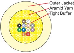
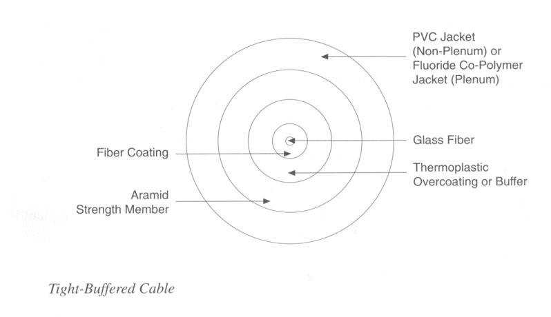
Indoor/Outdoor Tight Buffer
 
FIS now offers indoor/outdoor rated tight buffer cables in Riser and Plenum rated versions. These cables are flexible, easy to handle and simple to install. Since they do not use gel, the connectors can be terminated directly onto the fiber without difficult to use breakout kits. This provides an easy and overall less expensive installation. (Temperature rating -40ºC to +85ºC).
Indoor/Outdoor Breakout Cable
 
FIS indoor/outdoor rated breakout style cables are easy to install and simple to terminate without the need for fanout kits. These rugged and durable cables are OFNR rated so they can be used indoors, while also having a -40c to +85c operating temperature range and the benefits of fungus, water and UV protection making them perfect for outdoor applications. They come standard with 2.5mm sub units and they are available in plenum rated versions.
Corning Cable Systems Freedm LST Cables
 
Corning Cable Systems FREEDM® LST™ cables are OFNR-rated, UV-resistant, fully waterblocked indoor/outdoor cables. This innovative DRY™ cable with water blocking technology eliminates the need for traditional flooding compound, providing more efficient and craft-friendly cable preparation. Available in 62.5µm, 50µm, Singlemode and hybrid versions.
Krone Indoor Outdoor Dry Loose Tube Cable
 
KRONE’s innovative line of indoor/outdoor loose tube cables are designed to meet all the rigors of the outside plant environment, and the necessary fire ratings to be installed inside the building. These cables eliminate the gel filler of traditional loose tube style cables with super absorbent polymers.
Loose Tube Cable
 
Loose tube cable is designed to endure outside temperatures and high moisture conditions. The fibers are loosely packaged in gel filled buffer tubes to repel water. Recommended for use between buildings that are unprotected from outside elements. Loose tube cable is restricted from inside building use, typically allowing entry not to exceed 50 feet (check your local codes).
Aerial Cable/Self-Supporting
 
Aerial cable provides ease of installation and reduces time and cost. Figure 8 cable can easily be separated between the fiber and the messenger. Temperature range ( -55ºC to +85ºC)
Hybrid & Composite Cable
 
Hybrid cables offer the same great benefits as our standard indoor/outdoor cables, with the convenience of installing multimode and singlemode fibers all in one pull. Our composite cables offer optical fiber along with solid 14 gauge wires suitable for a variety of uses including power, grounding and other electronic controls.
Armored Cable
 
Armored cable can be used for rodent protection in direct burial if required. This cable is non-gel filled and can also be used in aerial applications. The armor can be removed leaving the inner cable suitable for any indoor/outdoor use. (Temperature rating -40ºC to +85ºC)
Low Smoke Zero Halogen (LSZH)
 
Low Smoke Zero Halogen cables are offered as as alternative for halogen free applications. Less toxic and slower to ignite, they are a good choice for many international installations. We offer them in many styles as well as simplex, duplex and 1.6mm designs. This cable is riser rated and contains no flooding gel, which makes the need for a separate point of termination unnecessary. Since splicing is eliminated, termination hardware and labor times are reduced, saving you time and money. This cable may be run through risers directly to a convenient network hub or splicing closet for interconnection.

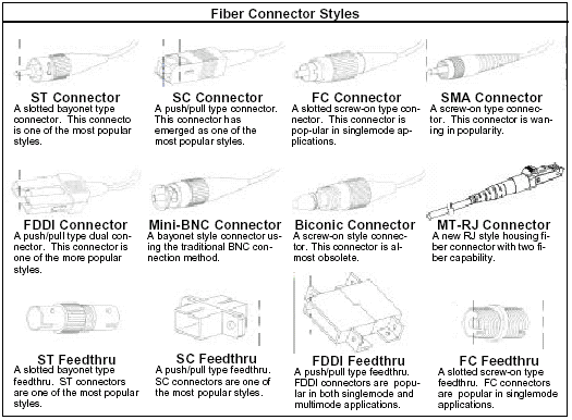
Konektor Patch Cord

Berikut ini macam-macam bantuk konektor dari Patch Cord Fiber Optic:

Single Mode dan Multimode


GAMBARAN SINGKAT DARI KEUNTUNGAN FIBER OPTIC CABLE  DENGAN TEMBAGA:
• SPEED: jaringan fiber optik beroperasi pada kecepatan tinggi - sampai ke gigabit


• BANDWIDTH: daya dukung besar


• JARAK: Sinyal dapat ditransmisikan lebih jauh tanpa perlu menjadi "segar" atau diperkuat.


• KEDAP: perlawanan lebih besar terhadap suara elektromagnetik seperti radio, motor atau kabel terdekat lainnya.


• PEMELIHARAAN: Kabel serat optik biaya jauh lebih sedikit untuk mempertahankan.


Dalam beberapa tahun terakhir telah menjadi jelas bahwa serat optik yang terus mengganti kawat tembaga sebagai sarana yang tepat untuk transmisi sinyal komunikasi. Fiber Optic dapat mencakup jarak jauh antara sistem telepon lokal serta menyediakan back bone untuk banyak sistem jaringan . Pengguna sistem lainnya termasuk layanan televisi kabel, kampus-kampus, universitas, gedung perkantoran, pabrik industri, dan perusahaan utilitas listrik.
Sebuah sistem fiber optic mirip dengan sistem kawat tembaga yang fiber optic gantikan. Perbedaannya adalah bahwa fiber optic menggunakan media cahaya untuk mengirimkan informasi ke melalui garis serat daripada menggunakan media elektronik untuk mengirimkan informasi ke melalui garis tembaga. Melihat komponen dalam rantai fiber optic akan memberikan pemahaman yang lebih baik tentang bagaimana sistem bekerja bersama dengan sistem berbasis kabel.
Pada salah satu ujung dari sistem ini adalah pemancar. Ini adalah tempat asal bagi informasi yang datang ke jalur fiber optic. Pemancar menerima informasi berupa kode elektronik yang datang dari kawat tembaga. Kemudian informasi diproses dan diterjemahkan  menjadi   kode ekuivalen cahaya. Sebuah dioda pemancar cahaya (LED) atau dioda injeksi-laser (ILD) dapat digunakan untuk menghasilkan cahaya. Dengan menggunakan lensa, cahaya disalurkan ke dalam media fiber optic di mana mereka melakukan perjalanan ke kabel. Lampu (near infrared) yang paling sering digunakan adalah 850nm untuk jarak pendek dan 1.300 nm untuk jarak yang lebih jauh pada kabel Multi-mode 1300nm dan untuk kabel single-mode 1.500 nm digunakan untuk untuk jarak yang lebih jauh.
Bayangkan sebuah kabel yang berada didalam gulungan karton yang sangat lama (dari gulungan dalam handuk kertas) yang dilapisi dengan cermin di dalamnya.
Jika Anda bersinar senter di salah satu ujungnya Anda dapat melihat cahaya keluar di ujung - bahkan jika itu sudah dibengkokkan sekitar sudut.

Cahaya bergerak dengan mudah di jalur fiberoptic dengan prinsip yang dikenal sebagai refleksi internal total. "Prinsip dari total refleksi internal menyatakan bahwa ketika sudut insiden melebihi nilai kritis, cahaya tidak bisa keluar dari kaca, melainkan cahaya memantul kembali masuk. Ketika prinsip ini diterapkan untuk pembangunan alur serat optik, hal ini memungkinkan untuk mengirimkan informasi ke bawah garis serat dalam bentuk media cahaya. Intinya harus berupa bahan yang sangat bening dan murni untuk cahaya atau dalam banyak kasus cahaya inframerah dekat (850nm, 1300nm dan 1500nm). inti dapat berupa Plastik (digunakan untuk jarak yang sangat pendek) tetapi sebagian besar terbuat dari kaca. Kaca fiber optic hampir selalu dibuat dari silika murni,. tetapi beberapa bahan lain, seperti fluorozirconate, fluoroaluminate, dan gelas chalcogenide, digunakan untuk panjang gelombang aplikasi inframerah.

Ada tiga jenis kabel fiber optik yang umum digunakan: single mode, multimode dan plastik (POF).

Kaca transparan atau serat plastik yang memungkinkan cahaya untuk dipandu dari satu ujung ke ujung dengan kerugian minimal.

Fungsi kabel fiber optic adalah sebagai "pemandu cahaya," membimbing cahayadan memperkenalkan pada salah satu ujung kabel sampai ujung lainnya. Sumber cahaya dapat menjadi dioda pemancar cahaya (LED)) atau laser.
Sumber cahaya berdenyut, dan penerima yang sensitif terhadap cahaya di ujung kabel yang lain mengubah cahaya kembali ke bentuk biner dari sinyal asli.
Sekalipun sinar laser bersinar melalui kabel serat optik kehilangan kekuatan, terutama melalui dispersi dan hamburan cahaya, dalam kabel itu sendiri. Semakin cepat berfluktuasi laser, semakin besar risiko dispersi. Penguat cahaya, yang disebut repeater, mungkin diperlukan untuk me-refresh sinyal dalam aplikasi tertentu.
Sementara kabel fiber optik itu sendiri telah menjadi lebih murah dari waktu ke waktu - panjang setara dengan biaya kabel tembaga tetapi tidak dalam kapasitas. Konektor kabel serat optik dan peralatan yang dibutuhkan untuk menginstal mereka masih lebih mahal daripada rekan-rekan tembaga mereka.
uni-mode fiber. Kabel singlemode berdiri sendiri (sebagian besar aplikasi menggunakan 2 serat) dari serat kaca dengan diameter sebesar 8,3 sampai 10 mikron yang memiliki satu cara penularan. Modus tunggal Fiber dengan diameter yang relatif sempit, di mana hanya satu mode akan menyebarkan biasanya 1310 atau 1550nm. Membawa bandwidth yang lebih tinggi dari serat multimode, tetapi membutuhkan sumber cahaya dengan lebar spektral yang sempit. Sinonim serat: mono-mode optik, serat single-mode, single-mode Waveguide optik, uni-mode serat.
Single Modem fber digunakan dalam berbagai aplikasi dimana data dikirim pada multi frekuensi (WDM Gelombang-Division Multiplexing-) jadi hanya satu kabel yang diperlukan - (single-mode pada satu serat tunggal)
serat single mode memberikan Anda tingkat transmisi yang lebih tinggi dan jarak hingga 50 kali lebih dari multimode, tetapi juga biaya lebih. Single-mode serat memiliki inti jauh lebih kecil dari multimode. Kecil inti dan tunggal cahaya-gelombang hampir menghilangkan distorsi yang didapat hasil dari cahaya yang tumpang tindih, memberikan redaman sinyal minimal dan kecepatan transmisi tertinggi dari setiap jenis kabel serat.

fiber optic single mode adalah serat optik di mana hanya yang terendah agar modus terikat dapat menyebarkan pada panjang gelombang yang menarik biasanya 1300 sampai 1320nm.

jump to single mode fiber page


Kabel Multi Mode  memiliki diameter sedikit lebih besar, dengan diameter umum dalam kisaran 50-ke-100 mikron untuk komponen membawa cahaya (di AS ukuran yang paling umum adalah 62.5um). Sebagian besar aplikasi di mana Multi-mode serat yang digunakan, 2 serat yang digunakan (WDM biasanya tidak digunakan pada serat multi-mode). POF adalah kabel berbasis plastik baru yang menjanjikan kinerja yang mirip dengan kabel kaca di berjalan sangat singkat, tetapi dengan biaya lebih rendah.
Serat multimode memberikan bandwidth yang tinggi pada kecepatan tinggi (10 sampai 100mbs - Gigabit ke 275m ke 2km) jarak menengah. Gelombang cahaya tersebar ke berbagai jalur, atau mode, saat mereka melakukan perjalanan melalui inti kabel itu biasanya 850 atau 1300nm. Diameter serat multimode Khas inti 50, 62,5, dan 100 mikrometer. Namun, dalam berjalan kabel panjang (lebih dari 3000 kaki [914,4 meter), beberapa jalur cahaya dapat menyebabkan distorsi sinyal pada sisi penerima, yang mengakibatkan transmisi data tidak jelas dan tidak lengkap sehingga desainer sekarang panggilan untuk serat single mode dalam aplikasi baru menggunakan Gigabit dan seterusnya.
Penggunaan fiber optic pada umumnya tidak tersedia sampai 1970 ketika Corning Glass Works mampu menghasilkan serat dengan kerugian sebesar 20 dB / km. Ini, diakui bahwa serat optik akan layak untuk transmisi telekomunikasi hanya jika kaca dapat dikembangkan begitu murni bahwa pelemahan akan 20dB/km atau kurang. Artinya, 1% cahaya akan tetap setelah menempuh perjalanan 1 km. Sekarang fiber optik memiliki atenuasi berkisar dari 0.5dB/km untuk 1000dB/km tergantung pada serat optik yang digunakan.
Aplikasi komunikasi serat optik telah meningkat dengan kecepatan tinggi, karena instalasi komersial pertama dari sistem serat optik pada tahun 1977. Perusahaan-perusahaan telepon mulai sejak awal, menggantikan sistem kawat tembaga lama mereka dengan garis serat optik. Perusahaan telepon saat ini menggunakan serat optik sepanjang sistem mereka sebagai arsitektur backbone dan sebagai koneksi jarak jauh antara sistem telepon kota.
Perusahaan televisi kabel juga mulai mengintegrasikan serat optik ke dalam sistem kabel mereka.Trunk yang menghubungkan kantor pusat umumnya telah diganti dengan serat optik. Beberapa penyedia telah mulai bereksperimen dengan serat ke tepi jalan menggunakan serat hibrida / koaksial. Seperti hibrida memungkinkan untuk integrasi serat dan koaksial di lokasi lingkungan. Lokasi ini, yang disebut node, akan memberikan penerima optik yang mengubah impuls cahaya kembali ke sinyal elektronik. Sinyal kemudian dapat diumpankan ke rumah individu melalui kabel koaksial.
Local Area Network (LAN) adalah kelompok kolektif komputer, atau sistem komputer, terhubung satu sama lain yang memungkinkan untuk penggunaan perangkat lunak  bersama atau basis data. Perguruan tinggi, universitas, gedung perkantoran, dan pabrik-pabrik industri, hanya untuk beberapa nama, semua menggunakan serat optik dalam sistem mereka LAN.
Perusahaan listrik adalah sebuah kelompok baru yang telah mulai memanfaatkan serat optik dalam sistem komunikasi mereka. Utilitas listrik yang paling sudah memiliki serat optik sistem komunikasi yang digunakan untuk memantau kekuatan mereka sistem grid.